Hyundai Venue: Engine Control System / Camshaft Position Sensor (CMPS). Repair procedures
| 1. |
Check signal waveform of CKPS and CMPS using a scan tool.
|
Specification : Refer to "Waveform"
|
|
| • |
DON’T remove the camshaft position sensor during engine running
or right after engine stops, or a scald by the flowed out engine
oil may occur.
|
|
| 1. |
Turn the ignition switch OFF and disconnect the battery negative (-)
cable.
|
| 2. |
Disconnect the camshaft position sensor connector (A).
|
| 3. |
Remove the installation bolt (B), and then remove the sensor.
|
Camshaft position sensor installation bolt :
7.8 - 11.8 N.m (0.8 - 1.2 kgf.m, 5.8 - 8.7 lb-ft)
|
[Bank 1 / Intake]
[Bank 1 / Exhaust]
|
| • |
Install the component with the specified torques.
|
| • |
Note that internal damage may occur when the component is dropped.
In this case, use it after inspecting.
|
|
| • |
Apply the engine oil to the O-ring.
|
|
| • |
Insert the sensor in the installation hole and be careful not
to damage when installation.
|
|
| • |
Be careful not to damage the sensor housing and the connector.
|
| • |
Be careful not to damage the O-ring.
|
|
| 1. |
Install in the reverse order of removal.
|
Description
Knocking is a phenomenon characterized by undesirable vibration and noise and
can cause engine damage. Knock Sensor (KS) is installed on the cylinder block
and senses engine knocking...
Other information:
TCM Connector
Connector [A]
Pin
Description
2
35R clutch control solenoid valve (35R/C_VFS)
4
26 brake control solenoid valve (26/B_VFS)
5
Underdrive brake control solenoid valve (UD/B_VFS)
8
Inhibitor switch signal S2 (R)
19
Line pressure control solenoid valve (LINE_VFS)
21
Input speed sensor power
22
Output speed sensor power
32
Torque converter control solenoid valve (T/CON_VFS)
33
VB (Battery voltage)
34
Solenoid supply power 2
37
Output speed sensor signal
38
Inhibitor switch signal S4 (D)
39
Inhibitor switch signal S1 (P)
40
Manual mode up shift
42
Manual mode select switch
43
Oil temperature sensor (+)
45
VB (Battery voltage)
46
ON/OFF solenoid valve A(SS-A)
47
Overdrive clutch control solenoid valve (OD/C_VFS)
48
VB (Battery voltage)
49
Solenoid supply power 1
52
Input speed sensor signal
54
Inhibitor switch signal S3 (N)
57
Manual mode down shift
58
Oil temperature sensor (-)
TCM Terminal input/ output signal
Connector [A]
Pin
Description
Condition
Input/output value
Type
Level
2
35R clutch control solenoid valve
(35R/C_VFS)
-
Output
0V/Battery voltage level
9V < Battery voltage level < 16V
4
26 brake control solenoid valve
(26/B_VFS)
-
Output
0V/Battery voltage level
9V < Battery voltage level < 16V
5
Underdrive brake control solenoid valve
(UD/B_VFS)
-
Output
0V/Battery voltage level
9V < Battery voltage level < 16V
8
Inhibitor switch signal S2 (R)
High
Input
0V/Battery voltage level
Low
9V < Battery voltage level < 16V
19
Line pressure control solenoid valve
(LINE_VFS)
-
Output
0V/Battery voltage level
9V < Battery voltage level < 16V
21
Input speed sensor power
ON
Power
0V/9V
OFF
22
Output speed sensor power
ON
Power
0V/9V
OFF
32
Torque converter control solenoid valve
(T/CON_VFS)
-
Output
0V/Battery voltage level
9V < Battery voltage level < 16V
34
Solenoid power 2
Power
0V/Battery voltage level
9V < Battery voltage level < 16V
37
Output speed sensor signal
High
Input
0...
..
Categories
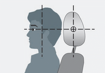
The vehicle’s front and rear seats have adjustable head restraints. The head
restraints provide comfort for passengers, but more importantly they are designed
to help protect passengers from whiplash and other neck and spinal injuries during
an accident, especially in a rear impact collision.
WARNING
To reduce the risk of serious injury or death in an accident, take the following
precautions when adjusting your head restraints:
Always properly adjust the head restraints for all passengers BEFORE
starting the vehicle.
NEVER let anyone ride in a seat with the head restraints removed or reversed.
read more


 Knock Sensor (KS). Description and operation