Hyundai Venue: Engine Control System / Description and operation
Hyundai Venue (QX) (2020-2025) Service Manual / Engine Control / Fuel System / Engine Control System / Description and operation
| Description |
If the Gasoline Engine Control system components (sensors, ECM, injector, etc.)
fail, interruption to the fuel supply or failure to supply the proper amount
of fuel for various engine operating conditions will result. The following situations
may be encountered.
| 1. |
Engine is hard to start or does not start at all.
|
| 2. |
Unstable idle.
|
| 3. |
Poor driveability
|
If any of the above conditions are noted, first perform a routine diagnosis
that includes basic engine checks (ignition system malfunction, incorrect engine
adjustment, etc.). Then, inspect the Gasoline Engine Control system components
with the HI-SCAN (Pro).
|

Malfunction Indicator Lamp (MIL)
| [EOBD] |
A malfunction indicator lamp illuminates to notify the driver that there is
a problem with the vehicle. However, the MIL will go off automatically after
3 subsequent sequential driving cycles without the same malfunction. Immediately
after the ignition switch is turned on (ON position - do not start), the MIL
will illuminate continuously to indicate that the MIL operates normally.
Faults with the following items will illuminate the MIL.
| – |
Catalyst
|
| – |
Fuel system
|
| – |
Mass Air Flow Sensor (MAFS)
|
| – |
Intake Air Temperature Sensor (IATS)
|
| – |
Engine Coolant Temperature Sensor (ECTS)
|
| – |
Throttle Position Sensor (TPS)
|
| – |
Upstream Oxygen Sensor
|
| – |
Upstream Oxygen Sensor Heater
|
| – |
Downstream Oxygen Sensor
|
| – |
Downstream Oxygen Sensor Heater
|
| – |
Injector
|
| – |
Misfire
|
| – |
Crankshaft Position Sensor (CKPS)
|
| – |
Camshaft Position Sensor (CMPS)
|
| – |
Evaporative Emission Control System
|
| – |
Vehicle Speed Sensor (VSS)
|
| – |
Idle Speed Control Actuator (ISCA)
|
| – |
Power Supply
|
| – |
ECM/ PCM
|
| – |
MT/AT Encoding
|
| – |
Acceleration Sensor
|
| – |
MIL-on Request Signal
|
| – |
Power Stage
|
|

| [NON-EOBD] |
A malfunction indicator lamp illuminates to notify the driver that there is
a problem with the vehicle. However, the MIL will go off automatically after
3 subsequent sequential driving cycles without the same malfunction. Immediately
after the ignition switch is turned on (ON position - do not start), the MIL
will illuminate continuously to indicate that the MIL operates normally.
Faults with the following items will illuminate the MIL
| – |
Heated oxygen sensor (HO2S)
|
| – |
Mass Air Flow sensor (MAFS)
|
| – |
Throttle position sensor (TPS)
|
| – |
Engine coolant temperature sensor (ECTS)
|
| – |
Idle speed control actuator (ISCA)
|
| – |
Injectors
|
| – |
ECM
|
|

[Inspection]
| 1. |
After turning ON the ignition key, ensure that the light illuminates
for about 5 seconds and then goes out.
|
| 2. |
If the light does not illuminate, check for an open circuit in the harness,
a blown fuse or a blown bulb.
|
Self-Diagnosis
The ECM monitors the input/output signals (some signals at all times and the
others under specified conditions). When the ECM detects an irregularity, it
records the diagnostic trouble code, and outputs the signal to the Data Link
connector. The diagnosis results can be read with the MIL or HI-SCAN (Pro).
Diagnostic Trouble Codes (DTC) will remain in the ECM as long as battery power
is maintained. The diagnostic trouble codes will, however, be erased when the
battery terminal or ECM connector is disconnected, or by the HI-SCAN (Pro).
|

The Relation Between DTC And Driving Pattern In EOBD System
| 1. |
When the same malfunction is detected and maintained during two sequential
driving cycles, the MIL will automatically illuminate.
|
| 2. |
The MIL will go off automatically if no fault is detected after 3 sequential
driving cycles.
|
| 3. |
A Diagnostic Trouble Code (DTC) is recorded in ECM memory when a malfunction
is detected after two sequential driving cycles. The MIL will illuminate
when the malfunction is detected on the second driving cycle.
If a misfire is detected, a DTC will be recorded, and the MIL will illuminate,
immediately after a fault is first detected.
|
| 4. |
A Diagnostic Trouble Code (DTC) will automatically erase from ECM memory
if the same malfunction is not detected for 40 driving cycles.
|

 Components and components location
Components Location
1. ECM (Engine Control Module)
2. Manifold Absolute Pressure Sensor (MAPS)
3. Intake Air Temperature Sensor (IATS)
4...
 Engine Control Module (ECM). Schematic diagrams
Engine Control Module (ECM)
[M/T]
ECM Terminal Function [M/T]
Connector [A]
Pin No
Description
Connected to
1
Injector (Cylinder #1) control output
Injector (Cylinder #1)
2
Sensor power (+5V)
Throttle Position Sensor (TPS) # 1, 2 [ETC module]
3
Sensor power (+5V)
Accelerator Position Sensor (APS) 1
4
Main Relay control output
Main Relay
5
-
-
6
Alternator signal input [FR]
Alternator
7
Engine coolant temperature sensor (ECTS) signal input
Engine coolant temperature sensor (ECTS)
8
Sensor ground
Manifold absolute pressure sensor (MAPS)
9
-
10
Sensor ground
Heated Oxygen Sensor (HO2S) [Bank 1 / Sensor 2]
11
-
12
-
13
CVVT Oil Control (OCV) Valve [Bank 1/Intake] control output
CVVT Oil Control Valve (OCV) [Bank 1 / Intake]
14
Sensor power (+5V)
Manifold absolute pressure sensor (MAPS)
15
Sensor power (+5V)
Accelerator Position Sensor (APS) #2
A/C Pressure Transducer (APT)
16
Sensor power (+5V)
CMPS [Bank 1 / Intake]
CMPS [Bank 1 / Exhaust]
17
Vehicle speed signal input
ABS/ESP Control Module [With ABS / ESP]
18
Battery voltage supply after ignition switch
Ignition Switch
19
Sensor ground
Camshaft Position Sensor (CMPS) [Bank 1 / Exhaust]
20
Sensor ground
A/C Pressure Transducer (APT)
21
Sensor ground
Battery sensor
22
-
23
-
24
-
25
Injector (Cylinder #2) control output
Injector (Cylinder #2)
26
Cooling Fan Relay [High] control output
Cooling Fan Relay [High]
27
Start relay control output (With smart key)
Start relay
28
Alternator control output [COM]
Alternator
29
C-CAN [Low]
Other control module, Data Link Connector (DLC),
30
-
31
Camshaft Position Sensor (CMPS) [Bank 1 / Exhaust] signal input
Camshaft Position Sensor (CMPS) [Bank 1 / Exhaust]
32
Sensor ground
Crankshaft Position Sensor (CKPS)
33
Crankshaft Position Sensor (CKPS) signal input
Crankshaft Position Sensor (CKPS)
34
Sensor ground
Throttle Position Sensor (TPS) 1, 2
35
Sensor ground
Accelerator Position Sensor (APS) 2
36
Sensor ground
Accelerator Position Sensor (APS) 1
37
Injector (Cylinder #4) control output
Injector (Cylinder #4)
38
-
39
Engine RPM signal output
Smart key Control Module
40
Immobilizer communication line
Immobilizer Control module [Without Smart Key]
Smart Key Control module [With Smart Key]
41
C-CAN [High]
Other control module, Data Link Connector (DLC)
42
-
43
Purge Control Solenoid Valve control output
Purge Control Solenoid Valve (PCSV)
44
-
45
Injector (Cylinder #3) control output
Injector (Cylinder #3)
46
Cooling Fan Relay [Low] control output
Cooling Fan Relay [Low]
47
Camshaft Position Sensor (CMPS) [Bank 1 / Intake] signal input
haft Position Sensor (CMPS) [Bank 1 / Intake]
48
Battery power (B+)
Battery
49
Heated Oxygen Sensor [Bank 1 / Sensor 1] Heater control output
Heated Oxygen Sensor [Bank 1 / Sensor 1]
50
Power Ground
Chassis Ground
51
-
52
Power Ground
Chassis Ground
53
Heated Oxygen Sensor [Bank 1 / Sensor 2] Heater control output
Heated Oxygen Sensor [Bank 1 / Sensor 2]
54
CVVT Oil Control (OCV) Valve [Bank 1 / Exhaust] control output
CVVT Oil Control Valve (OCV) [Bank 1 / Exhaust]
55
Battery voltage supply after main relay
Main relay
56
Battery voltage supply after main relay
Main relay
Connector [B]
Pin No
Description
Connected to
1
Sensor ground
Engine Coolant Temperature Sensor (ECTS)
2
Throttle position sensor (TPS) #2 signal input
Throttle position sensor (TPS) #2 [ETC Module]
3
Manifold absolute pressure sensor (MAPS) signal input
Manifold absolute pressure sensor (MAPS)
4
A/C Pressure Transducer (APT) signal input
A/C Pressure Transducer (APT)
5
-
6
-
7
Accelerator Position Sensor (APS) #1 signal input
Accelerator Position Sensor (APS) #1
8
-
9
-
10
-
11
Electric Load signal input (Defrost)
A/C Control Module, Outside Mirror
12
Brake switch 1 signal input
Brake lamp swtich , Brake switch
13
Heated Oxygen Sensor [Bank 1 / Sensor 2] signal input
Heated Oxygen Sensor [Bank 1 / Sensor 2]
14
Battery Sensor Temperature signal input
Battery sensor
15
Intake air temperature sensor (IATS) signal input
Intake Air temperature sensor (IATS)
16
Battery Sensor Current Direct signal input
Battery sensor
17
-
18
Accelerator Position Sensor (APS) #2 signal input
Accelerator Position Sensor (APS) #2
19
-
20
-
21
-
22
Throttle position sensor (TPS) #1 signal input
Throttle position sensor (TPS) #1
23
Brake Lamp Switch signal input
Brake Switch
24
Start switch signal input
Ignition switch
25
Sensor ground
Heated Oxygen Sensor [Bank 1 / Sensor 1]
26
-
27
Sensor ground
Knock sensor (KS)
28
-
29
Wheel speed sensor [B] signal input
Front wheel speed sensor (RH) [Without ABS]
30
Wheel speed sensor [A] signal input
Front wheel speed sensor (RH) [Without ABS]
31
-
32
Sensor ground
Camshaft Position Sensor (CMPS) [Bank 1 / Intake]
Camshaft Position Sensor (CMPS) [Bank 1 / Exhaust]
33
Power Ground
Chassis Ground
34
Clutch Switch signal input
Clutch switch [M...
Other information:
Hyundai Venue (QX) (2020-2025) Service Manual: Components and components location
Components 1. Front door trim 2. Front door module 3. Front door quadrant inner cover 4. Front door hinge 5. Front door inside weatherstrip 6. Front door outside weatherstrip 7. Front door body side weatherstrip 8...
Hyundai Venue (QX) (2020-2025) Service Manual: Rear Washer Switch. Repair procedures
..
Categories
- Manuals Home
- 1st Generation Venue Owners Manual
- 1st Generation Venue Service Manual
- Remote start
- Immobilizer System
- Liftgate
- New on site
- Most important about car
Master warning mode
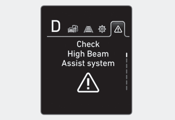
This warning light informs the driver the following situations.
-- Forward Collision-Avoidance Assist system malfunction (if equipped)
-- Forward Collision-Avoidance Assist radar blocked (if equipped)
-- Blind-Spot Collision Warning system malfunction (if equipped)
-- Blind-Spot Collision Warning radar blocked (if equipped)
-- Lamp malfunction (if equipped)
-- High Beam Assist malfunction (if equipped)
-- Tire Pressure Monitoring System (TPMS) malfunction (if equipped)

Copyright © 2025 www.hvenueqx.com