Hyundai Venue: Intake And Exhaust System / Exhaust Manifold. Repair procedures

Hyundai Venue (QX) (2020-2025) Service Manual / Engine Mechanical System / Intake And Exhaust System / Exhaust Manifold. Repair procedures

Removal and Installation
1.
Remove the engine cover.
2.
Disconnect the battery negative terminal.
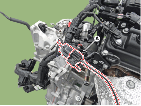
3.
Disconnect the front oxygen sensor connector (A).

Hyundai Venue. Exhaust Manifold. Repair procedures

4.
Remove the front muffler.
(Refer to Intake and Exhaust Manifold - "Front Muffler")
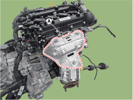
5.
Remove the exhaust manifold heat protector (A).
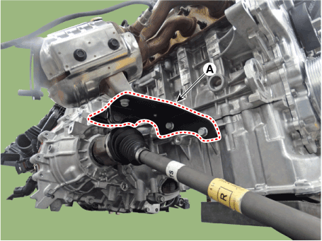
Tightening torque :
9.8 - 11.8 N.m (1.0 - 1.2 kgf.m, 7.2 - 8.7 lb-ft)

Hyundai Venue. Exhaust Manifold. Repair procedures

6.
Remove the exhaust manifold stay (A).
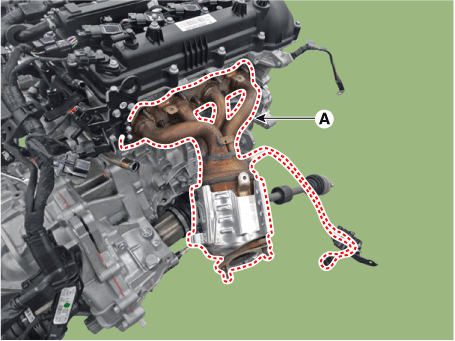
Tightening torque :
39.2 - 49.0 N.m (4.0 - 5.0 kgf.m, 28.9 - 36.2 lb-ft)

Hyundai Venue. Exhaust Manifold. Repair procedures

7.
Remove the exhaust manifold (A) and gasket.
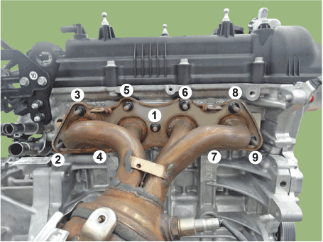
Tightening torque :
29.4 - 41.2 N.m (3.0 - 4.2 kgf.m, 21.7 - 30.4 lb-ft)

Hyundai Venue. Exhaust Manifold. Repair procedures

Hyundai Venue. Exhaust Manifold. Repair procedures   
When installing the exhaust manifold, with a new gasket.
When installing the exhaust manifold, tighten the nuts with pre-torque first and then tighten the nuts with specified torque in the sequence shown.

Hyundai Venue. Exhaust Manifold. Repair procedures

8.
Install in the reverse order of removal.

    Exhaust Manifold. Components and components location

    ..

    Muffler. Components and components location

    Components 1. Front muffler 2. Catalytic converter & center muffler assembly 3. Rear Muffler 4. Hanger 5...

    Other information:

    Hyundai Venue (QX) (2020-2025) Service Manual: Audio Unit. Components and components location


    ..

    Hyundai Venue (QX) (2020-2025) Service Manual: Engine Control Module (ECM). Schematic diagrams


    Engine Control Module (ECM) [M/T] ECM Terminal Function [M/T] Connector [A] Pin No Description Connected to 1 Injector (Cylinder #1) control output Injector (Cylinder #1) 2 Sensor power (+5V) Throttle Position Sensor (TPS) # 1, 2 [ETC module] 3 Sensor power (+5V) Accelerator Position Sensor (APS) 1 4 Main Relay control output Main Relay 5 - - 6 Alternator signal input [FR] Alternator 7 Engine coolant temperature sensor (ECTS) signal input Engine coolant temperature sensor (ECTS) 8 Sensor ground Manifold absolute pressure sensor (MAPS) 9 - 10 Sensor ground Heated Oxygen Sensor (HO2S) [Bank 1 / Sensor 2] 11 - 12 - 13 CVVT Oil Control (OCV) Valve [Bank 1/Intake] control output CVVT Oil Control Valve (OCV) [Bank 1 / Intake] 14 Sensor power (+5V) Manifold absolute pressure sensor (MAPS) 15 Sensor power (+5V) Accelerator Position Sensor (APS) #2 A/C Pressure Transducer (APT) 16 Sensor power (+5V) CMPS [Bank 1 / Intake] CMPS [Bank 1 / Exhaust] 17 Vehicle speed signal input ABS/ESP Control Module [With ABS / ESP] 18 Battery voltage supply after ignition switch Ignition Switch 19 Sensor ground Camshaft Position Sensor (CMPS) [Bank 1 / Exhaust] 20 Sensor ground A/C Pressure Transducer (APT) 21 Sensor ground Battery sensor 22 - 23 - 24 - 25 Injector (Cylinder #2) control output Injector (Cylinder #2) 26 Cooling Fan Relay [High] control output Cooling Fan Relay [High] 27 Start relay control output (With smart key) Start relay 28 Alternator control output [COM] Alternator 29 C-CAN [Low] Other control module, Data Link Connector (DLC), 30 - 31 Camshaft Position Sensor (CMPS) [Bank 1 / Exhaust] signal input Camshaft Position Sensor (CMPS) [Bank 1 / Exhaust] 32 Sensor ground Crankshaft Position Sensor (CKPS) 33 Crankshaft Position Sensor (CKPS) signal input Crankshaft Position Sensor (CKPS) 34 Sensor ground Throttle Position Sensor (TPS) 1, 2 35 Sensor ground Accelerator Position Sensor (APS) 2 36 Sensor ground Accelerator Position Sensor (APS) 1 37 Injector (Cylinder #4) control output Injector (Cylinder #4) 38 - 39 Engine RPM signal output Smart key Control Module 40 Immobilizer communication line Immobilizer Control module [Without Smart Key] Smart Key Control module [With Smart Key] 41 C-CAN [High] Other control module, Data Link Connector (DLC) 42 - 43 Purge Control Solenoid Valve control output Purge Control Solenoid Valve (PCSV) 44 - 45 Injector (Cylinder #3) control output Injector (Cylinder #3) 46 Cooling Fan Relay [Low] control output Cooling Fan Relay [Low] 47 Camshaft Position Sensor (CMPS) [Bank 1 / Intake] signal input haft Position Sensor (CMPS) [Bank 1 / Intake] 48 Battery power (B+) Battery 49 Heated Oxygen Sensor [Bank 1 / Sensor 1] Heater control output Heated Oxygen Sensor [Bank 1 / Sensor 1] 50 Power Ground Chassis Ground 51 - 52 Power Ground Chassis Ground 53 Heated Oxygen Sensor [Bank 1 / Sensor 2] Heater control output Heated Oxygen Sensor [Bank 1 / Sensor 2] 54 CVVT Oil Control (OCV) Valve [Bank 1 / Exhaust] control output CVVT Oil Control Valve (OCV) [Bank 1 / Exhaust] 55 Battery voltage supply after main relay Main relay 56 Battery voltage supply after main relay Main relay Connector [B] Pin No Description Connected to 1 Sensor ground Engine Coolant Temperature Sensor (ECTS) 2 Throttle position sensor (TPS) #2 signal input Throttle position sensor (TPS) #2 [ETC Module] 3 Manifold absolute pressure sensor (MAPS) signal input Manifold absolute pressure sensor (MAPS) 4 A/C Pressure Transducer (APT) signal input A/C Pressure Transducer (APT) 5 - 6 - 7 Accelerator Position Sensor (APS) #1 signal input Accelerator Position Sensor (APS) #1 8 - 9 - 10 - 11 Electric Load signal input (Defrost) A/C Control Module, Outside Mirror 12 Brake switch 1 signal input Brake lamp swtich , Brake switch 13 Heated Oxygen Sensor [Bank 1 / Sensor 2] signal input Heated Oxygen Sensor [Bank 1 / Sensor 2] 14 Battery Sensor Temperature signal input Battery sensor 15 Intake air temperature sensor (IATS) signal input Intake Air temperature sensor (IATS) 16 Battery Sensor Current Direct signal input Battery sensor 17 - 18 Accelerator Position Sensor (APS) #2 signal input Accelerator Position Sensor (APS) #2 19 - 20 - 21 - 22 Throttle position sensor (TPS) #1 signal input Throttle position sensor (TPS) #1 23 Brake Lamp Switch signal input Brake Switch 24 Start switch signal input Ignition switch 25 Sensor ground Heated Oxygen Sensor [Bank 1 / Sensor 1] 26 - 27 Sensor ground Knock sensor (KS) 28 - 29 Wheel speed sensor [B] signal input Front wheel speed sensor (RH) [Without ABS] 30 Wheel speed sensor [A] signal input Front wheel speed sensor (RH) [Without ABS] 31 - 32 Sensor ground Camshaft Position Sensor (CMPS) [Bank 1 / Intake] Camshaft Position Sensor (CMPS) [Bank 1 / Exhaust] 33 Power Ground Chassis Ground 34 Clutch Switch signal input Clutch switch [M...

    Categories

    Vehicle Identification Number (vin), Vehicle Certification Label

    Vehicle Identification Number (vin)

    Hyundai Venue. Vehicle Identification Number (vin), Vehicle Certification Label

    Frame number

    read more


    Copyright © 2025 www.hvenueqx.com