Hyundai Venue: Front Suspension System / Sub Frame. Repair procedures
Hyundai Venue (QX) (2020-2025) Service Manual / Suspension System / Front Suspension System / Sub Frame. Repair procedures
| Removal |
| 1. |
Loosen the wheel nuts slightly.
Raise the vehicle, and make sure it is securely supported.
|
| 2. |
Remove the front wheel and tire (A) from front hub.
|

| 3. |
Disconnect the stabilizer link with the front strut assembly after loosening
the nut (A).
|

| 4. |
Remove the tie rod end ball joint.
|
| 5. |
Loosen the lower arm nut (A) and then remove the lower arm ball joint
by using SST(09568-1S100).
|
| 6. |
Loosen the bolt (A) and then disconnect the universal joint assembly
from the pinion of the steering gear box.
|

| 7. |
Remove the engine room under cover (A).
(Refer to Engine Mechanical System - "Engine Room Under Cover")
|
| 8. |
Remove the heated protector (A).
|
| 9. |
Remove the muffler rubber hanger (A).
|
| 10. |
Remove the roll rod bracket (C) by loosening the bolt (A), (B).
|
| 11. |
Remove the subframe by loosening the mounting bolts and nuts.
|

| 12. |
Loosen the mounting bolts and then remove the stabilizer bar (A).
|
| 13. |
Remove the heated protector (A).
|
| 14. |
Remove the steering gearbox (A) from the front sub frame by loosening
the mounting bolts.
|
| 15. |
Remove the front lower arm (A) from the sub frame.
|
| Installation |
| 1. |
Install in the reverse order of removal.
|
| 2. |
Check the alignment.
(Refer to Suspension System - "Alignment")
|
 Front Stabilizer Bar. Repair procedures
Removal
1.
Loosen the wheel nuts slightly.
Raise the vehicle, and make sure it is securely supported.
2...
 Rear Shock Absorber. Components and components location
Components
1. Rear shock absorber
2. Dust cover
3. Spacer
4. Bumper rubber
5. Bumper rubber cover
6. Insulator assembly
7...
Other information:
Hyundai Venue (QX) (2020-2025) Owners Manual: Operating Door Locks from Outside the Vehicle
Mechanical key If you lock the driver’s door with a mechanical key, all vehicle doors will lock. If you unlock the driver’s door with a mechanical key, you can open and close the driver’s door only. Once the doors are unlocked, they may be opened by pulling the door handle...
Hyundai Venue (QX) (2020-2025) Service Manual: Injector. Repair procedures
Inspection 1. Turn ignition switch OFF. 2. Disconnect injector connector. 3. Measure resistance between injector terminals 1 and 2. 4. Check that the resistance is within the specification...
Categories
- Manuals Home
- 1st Generation Venue Owners Manual
- 1st Generation Venue Service Manual
- Operating Door Locks from Outside the Vehicle
- Trip Computer
- Liftgate
- New on site
- Most important about car
Smart Key
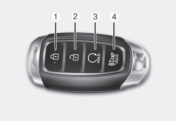
Your HYUNDAI uses a Smart Key, which you can use to lock or unlock the driver and passenger doors or the rear liftgate.
1. Door Lock
2. Door Unlock
3. Remote start

Copyright © 2025 www.hvenueqx.com