Hyundai Venue: Heating and Air Conditioning / Instrument panel vents
Hyundai Venue (QX) (2020-2025) Owners Manual / Convenient Features / Manual Climate Control System / Heating and Air Conditioning / Instrument panel vents
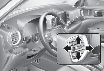
The instrument panel vent air flow can be directed up/down or left/right using the vent adjustment lever.
The air flow can also be CLOSED using the vent adjustment lever. The instrument panel air vents are the “clickto- close” type.
To CLOSE the instrument panel vents perform the following:
-- For the driver side vents, slide the vent adjustment lever to the left until
it clicks.
-- For the passenger side vents, slide the vent adjustment lever to the right until
it clicks.
 Heating and Air Conditioning
1. Start the engine.
2. Set the mode to the desired position. To improve the effectiveness of heating
and cooling, select the mode according to the following:
-- Heating:
-- Cooling:
3...

Other information:
Hyundai Venue (QX) (2020-2025) Service Manual: Repair procedures
Removal 1. Loosen the wheel nuts slightly. Raise the vehicle, and make sure it is securely supported. 2. Remove the front wheel and tire (A) from front hub. Tightening torque : 107...
Hyundai Venue (QX) (2020-2025) Service Manual: Engine Room Under Cover. Repair procedures
Removal and Installation 1. Remove the engine room under cover (A). Tightening torque : 3.9 - 5.9 N.m (0.4 - 0.6 kgf.m, 2.9 - 4.3 lb-ft) 2. Installation is reverse order of removal...
Categories
- Manuals Home
- 1st Generation Venue Owners Manual
- 1st Generation Venue Service Manual
- Smart Key
- Rear Combination Light Bulb Replacement
- Theft-Alarm System
- New on site
- Most important about car
Fuel gauge
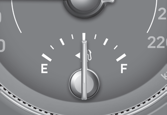
This gauge indicates the approximate amount of fuel remaining in the fuel tank.
Information
The fuel tank capacity is given in chapter 2. The fuel gauge is supplemented by a low fuel warning light, which will illuminate when the fuel tank is nearly empty. On inclines or curves, the fuel gauge pointer may fluctuate or the low fuel warning light may come on earlier than usual due to the movement of fuel in the tank.
Copyright © 2025 www.hvenueqx.com