Hyundai Venue: Cylinder Head Assembly / Repair procedures
Valve Clearance Inspection and Adjustment
| • |
Inspect and adjust the valve clearance when the engine is cold
(Engine coolant temperature : 20°C) and cylinder head is installed
on the cylinder block.
|
|
| 1. |
Remove the cylinder head cover.
(Refer to Cylinder Head Assembly - "Cylinder Head Cover")
|
| 2. |
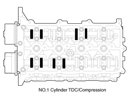
Set No.1 cylinder to TDC/compression.
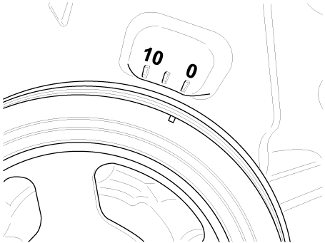
| (1) |
Turn the crankshaft pulley and align its groove with the timing
mark of the timing chain cover.
|
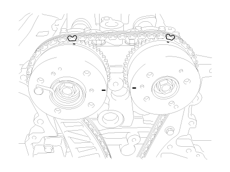
| (2) |
Check that the marks of the camshaft timing sprockets are in
straight line on the cylinder head surface as shown in the illustration.
If not, turn the crankshaft one revolution (360°).
|
|
| 3. |
Inspect the valve clearance.
| (1) |
Check only the intake valves of the 1st and 2nd cylinders and
exhaust valves of the 1st and 3rd cylinders for their clearance.
| •
|
Using a thickness gauge, measure the clearance between
the tappet and the base circle of camshaft.
|
| •
|
Record the out-of-specification valve clearance measurements.
They will be used later to determine the required tappet
for adjusting.
|
|
Valve clearance specification (Engine coolant temperature
: 20°C [68°F])
Limit
Intake : 0.17 - 0.23 mm (0.0067 - 0.0091 in.)
Exhaust : 0.22 - 0.28 mm (0.0087 - 0.0110 in.)
|
|
| (2) |
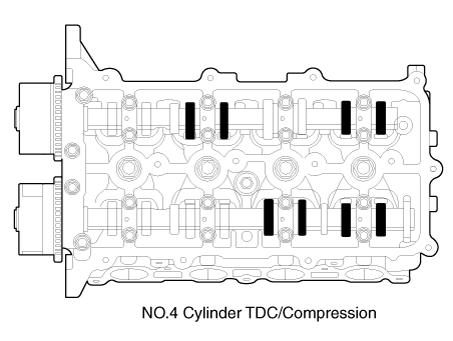
Turn the crankshaft pulley one revolution (clockwise 360°) and
align its groove with timing mark of the timing chain cover.
|
| (3) |
Check the intake valves of the 3rd and 4th cylinders and exhaust
valves of the 2nd and 4th cylinders for their clearance.
|
|
| 4. |
Adjust the intake and exhaust valve clearance.
| (1) |
Set the No.1 cylinder to the TDC/compression position.
|
| (2) |
Put paint marks on the timing chain links (2 places) that meet
with the timing marks of the intake, exhaust camshaft sprockets.
|
| (3) |
Remove the exhaust camshaft sprocket bolt.
|
| (4) |
Remove the service hole bolt of the timing chain cover.
|
• |
The bolt must not be reused once it has been
assembled.
|
|
|
| (5) |
Insert a thin rod in the service hole of the timing chain cover
and release the ratchet.
|
| (6) |
Remove the exhaust camshaft sprocket.
|
| (7) |
Remove the OCV valve adapter (A).
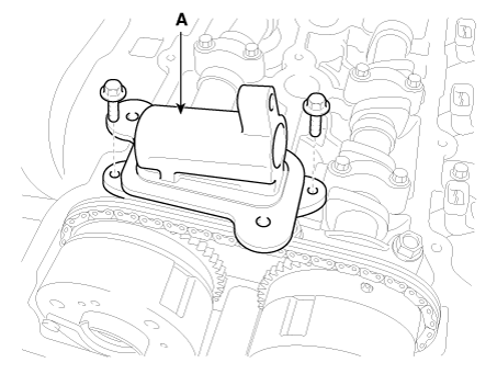
|
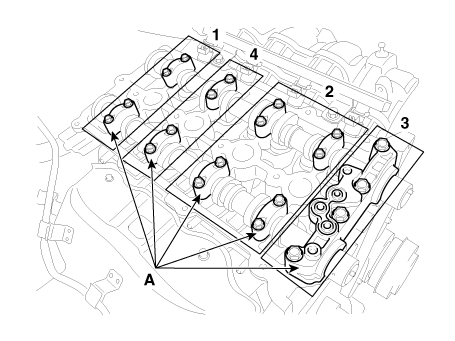
| (8) |
Remove the camshaft bearing caps (A) with the order below.
|
| (9) |
Remove the exhaust camshaft.
|
| (10) |
Remove the intake camshaft and CVVT module.
|
• |
When disconnecting the timing chain from the
camshaft timing sprocket, hold the timing chain.
|
|
|
| (11) |
Tie a timing chain with a string.
|
• |
Be careful not to drop anything inside timing
chain cover.
|
|
|
| (12) |
Measure the thickness of the removed tappet using a micrometer.
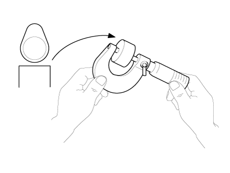
|
| (13) |
Calculate the thickness of a new tappet so that the valve clearance
comes within the specificified value.
|
Valve clearance (Engine coolant temperature : 20°C)
T : Thickness of removed tappet
A : Measured valve clearance
N : Thickness of new tappet
Intake : N = T + [A - 0.20 mm (0.0079 in.)]
Exhaust : N = T + [A - 0.25 mm (0.0098 in.)]
|
|
| (14) |
Select a new tappet with a thickness as close as possible to
the caculated value.
|
• |
Shims are available in 41size increments of
0.015mm (0.0006in.) from 3.00mm (0.118in.) to
3.600mm (0.1417in.)
|
|
|
| (15) |
Place a new tappet on the cylinder head.
|
| (16) |
Hold the timing chain, and place the intake camshaft and CVVT
module assembly.
|
| (17) |
Align the matchmarks on the timing chain and camshaft timing
sprocket.
|
| (18) |
Install the exhaust camshaft.
|
| (19) |
Install the exhaust camshaft sprocket.
|
Tightening torque :
63.7 - 73.5N.m (6.5 - 7.5kgf.m, 47.0 - 54.2lb-ft)
|
|
| (20) |
Install the camshaft bearing caps with the order below.
|
Tightening torque :
M6 bolts :
11.8 - 13.7N.m (1.2 - 1.4kgf.m, 8.7 - 10.1lb-ft)
M8 bolts :
18.6 - 22.6N.m (1.9 - 2.3kgf.m, 13.7 - 16.6lb-ft)
|
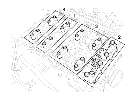
|
| (21) |
Install the service hole bolt.
|
Tightening torque :
11.8 - 14.7N.m (1.2 - 1.5kgf.m, 8.7 - 10.8lb-ft)
|
|
| (22) |
Turn the crankshaft two turns in the operating direction(clockwise)
and realign crankshaft sprocket and camshaft sprocket timing
marks.
|
| (23) |
Recheck the valve clearance.
|
Valve clearance (Engine coolant temperature : 20°C)
[Specification]
Intake : 0.17 - 0.23mm (0.0067 - 0.0091in.)
Exhaust : 0.22 - 0.28mm (0.0087 - 0.0110in.)
|
|
|
Components
1. Cylinder head cover
2. Cylinder head cover gasket
3. Cylinder head assembly
4. Cylinder head gasket
5...
Other information:
..
Cooling / Ventilation
1. Select the Face Level mode.
2. Set the air intake control to fresh mode.
3. Set the temperature control to the desired position.
4. Set the fan speed control to the desired speed.
Heating
1. Select the Floor Level mode...
Categories
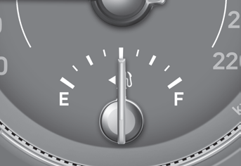
This gauge indicates the approximate amount of fuel remaining in the fuel tank.
Information
The fuel tank capacity is given in chapter 2.
The fuel gauge is supplemented by a low fuel warning light, which will
illuminate when the fuel tank is nearly empty.
On inclines or curves, the fuel gauge pointer may fluctuate or the low
fuel warning light may come on earlier than usual due to the movement of fuel
in the tank.
read more


 Components and components location