Hyundai Venue: Clutch Cover And Disc / Repair procedures
Hyundai Venue (QX) (2020-2025) Service Manual / Clutch System / Clutch Cover And Disc / Repair procedures
| Removal |
| 1. |
Remove the manual transaxle assembly.
(Refer to Manual Transaxle System - "Manual Transaxle")
|
| 2. |
Remove the clutch cover assembly after loosening the bolts.
|


| Inspection |
| 1. |
Inspect diaphragm spring wear which is in contact with a concentric
slave cylinder bearing.
|
| 2. |
Check the clutch cover and disc surface for wear or cracks.
|
| 3. |
Check the clutch disc lining for slipping or oil marks.
|
| 4. |
Measure the depth from a clutch lining surface to a rivet. If the measured
value is less than the specification below, replace it.
|
| Installation |
|

| 1. |
Apply grease on a disc spline part and transaxle input shaft spline
part as required.
|

| 2. |
Install the clutch disc and the cover with SST (A: 09411-1P000).
|


| 3. |
Install the clutch cover mounting bolts.
|

| 4. |
Remove the clutch disc guide SST (No.: 09411-1P000).
|
| 5. |
Install the transaxle assembly.
(Refer to Manual Transaxle System - "Manual Transaxle")
|


Other information:
Hyundai Venue (QX) (2020-2025) Service Manual: Components and components location
..
Hyundai Venue (QX) (2020-2025) Owners Manual: Resetting the sunroof
The sunroof may need to be reset if the following conditions occur: -- The battery is discharged or disconnected or the sunroof fuse has been replaced or disconnected -- The sunroof control lever is not operating correctly To reset the sunroof, perform the following steps: 1...
Categories
- Manuals Home
- 1st Generation Venue Owners Manual
- 1st Generation Venue Service Manual
- Liftgate
- Check Tire Pressure
- Smart Key
- New on site
- Most important about car
Head Restraints
The vehicle’s front and rear seats have adjustable head restraints. The head restraints provide comfort for passengers, but more importantly they are designed to help protect passengers from whiplash and other neck and spinal injuries during an accident, especially in a rear impact collision.
WARNING
To reduce the risk of serious injury or death in an accident, take the following precautions when adjusting your head restraints:
Always properly adjust the head restraints for all passengers BEFORE starting the vehicle. NEVER let anyone ride in a seat with the head restraints removed or reversed.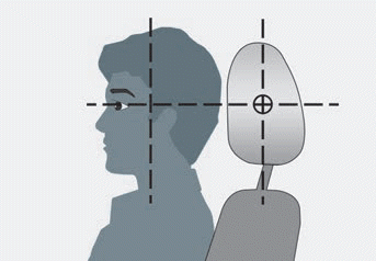

Copyright © 2025 www.hvenueqx.com