Hyundai Venue: Automatic Transaxle Control System / Shift Cable. Repair procedures
| 1. |
Turn OFF ignition switch and then diconnect the battery negative (-)
cable.
|
| 2. |
Remove the air cleaner and air duct.
| (1) |
Remove the air duct (A).
|
| (2) |
Disconnect the breather hose (B) and air intake hose (C).
|
| (3) |
Remove the air cleaner assembly (D).
|
Tightening torque :
Hose clamp bolt (C):
2.9 - 4.9 N.m (0.3 - 0.5 kgf.m, 2.1 - 3.6 lb-ft)
Air cleaner assembly bolts (D) :
3.9 - 5.9 N.m (0.4 - 0.6 kgf.m, 2.9 - 4.3 Ib-ft)
|
|
|
| 3. |
Remove the battery (+) terminal (A).
|
Tightening torque :
7.8 - 9.8 N.m (0.8 - 1.0 kgf.m, 5.8 - 7.2 lb-ft)
|
|
| 4. |
Remove the battery mounting bracket (A) and the battery (B).
|
Tightening torque :
9.0 - 14.0 N.m (0.9 - 1.4 kgf.m, 6.6 - 10.3 Ib-ft)
|
|
| 5. |
Remove the ECM.
| (1) |
Disconnect the ECM connector (A).
|
| (2) |
Loosen the mounting bolts (B) and then removing the ECM bracket
assembly.
|
|
Tightening torque :
9.8 - 11.8 N.m (1.0 - 1.2 kgf.m, 7.2 - 8.7 lb-ft)
|
|
| 6. |
Remove the battery tray.
| (1) |
Loosen the mounting bolt (A) and then removing the battery (+)
terminal bracket.
|
Tightening torque :
8.0 - 10.0 N.m (0.8 - 1.0 kgf.m, 5.9 - 7.4 lb-ft)
|
|
| (2) |
Loosen the bolts and then removing the battery tray (A).
|
Tightening torque :
8.8 - 13.7 N.m (0.9 - 1.4 kgf.m, 6.5 - 10.1 Ib-ft)
|
|
|
| 7. |
Remove the nut (A) from the manual control lever.
|
| 8. |
Remove the shift cable (B) from the bracket (C) at transaxle side.
|
| 9. |
Remove the shift knob & boots (A).
|
| 10. |
Remove the floor console assembly.
(Refer to Body - "Floor Consol")
|
| 11. |
Disconnect the connector (A).
|
| 12. |
Separate the air duct (A) from the both side.
|
| 13. |
Separate the shift cable.
| (1) |
Remove the snap pin (A).
|
| (2) |
Separate the shift cable (B).
|
|
| 14. |
Disconnect the shift cable retainer (A) after removing the nuts.
|
| 15. |
Remove the shift cable by pulling it toward the interior.
|
| 1. |
Install the shift cable retainer (A).
|
Tightening torque :
11.8 - 14.7 N.m (1.2 - 1.5 kgf.m, 8.7 - 10.8 lb-ft)
|

| •
|
Install the cable after placing the shift lever and
the manual control lever in the N position.
|
|
|
| 2. |
Install the shift cable (A) in the shifter lever.
| •
|
Lug must assemble upward.
|
| •
|
When assembling the snap pin, be careful about the correct
direction.
- The band portion (A) must point to the front of the
vehicle.
- The band portion (A) must point outwards.
|
|
|
| 3. |
Install the air duct (A).

|
| 4. |
Install the shift knob & boots (A).
|
| 5. |
Install the shift cable (B) in the cable bracket (C).
|
| 6. |
Align the hole (E) in the manual control lever with the "N" position
hole (G) of the inhibitor switch and then insert the inhibitor switch
guide pin (SST No: 09480-A3800).
|
| 7. |
Lightly tighten the nut (A) after connected the shift cable (B) in the
manual control lever (D).
|
| 8. |
Tighten the nut (A) to the specified torque.
|
Tightening torque :
9.8 - 13.7 N.m (1.0 - 1.4 kgf.m, 7.2 - 10.1 lb-ft)
|
|
| 9. |
Remove the inhibitor switch guide pin (SST No.: 09480-A3800) from the
hole.
|
| 10. |
Install the battery tray.
| (1) |
Tighten the bolts and then install the battery tray (A).
|
Tightening torque :
8.8 - 13.7 N.m (0.9 - 1.4 kgf.m, 6.5 - 10.1 Ib-ft)
|

|
| (2) |
Tighten the mounting bolt (A) and then install the battery (+)
terminal bracket.
|
Tightening torque :
8.0 - 10.0 N.m (0.8 - 1.0 kgf.m, 5.9 - 7.4 lb-ft)
|

|
|
| 11. |
Install the ECM.
| (1) |
Connect the ECM connector (A).
|
| (2) |
Tighten the mounting bolts (B) and then install the ECM bracket
assembly.
|
|
Tightening torque :
9.8 - 11.8 N.m (1.0 - 1.2 kgf.m, 7.2 - 8.7 lb-ft)
|

|
| 12. |
Install the battery (B) and mounting bracket (A).
|
Tightening torque :
9.0 - 14.0 N.m (0.9 - 1.4 kgf.m, 6.6 - 10.3 Ib-ft)
|

|
| 13. |
Install the battery (+) terminal (A).
|
Tightening torque :
7.8 - 9.8 N.m (0.8 - 1.0 kgf.m, 5.8 - 7.2 lb-ft)
|

|
| 14. |
Install the air cleaner and air duct.
| (1) |
Install the breather hose (B) and air intake hose (C).
|
| (2) |
Install the air cleaner assembly (D).
|
Tightening torque :
Hose clamp bolt (C):
2.9 - 4.9 N.m (0.3 - 0.5 kgf.m, 2.1 - 3.6 lb-ft)
Air cleaner assembly bolts (D) :
3.9 - 5.9 N.m (0.4 - 0.6 kgf.m, 2.9 - 4.3 Ib-ft)
|

|
| (3) |
Install the air duct (A).

|
|
| 15. |
Check that operating surely at each range of the inhibitor switch corresponding
to each position of shift lever.
|
Components Location
1. Shift lever knob & boots
2. Shift lever assembly
3. Shift cable
4. Manual control lever
5...
Other information:
..
Seat belt warning light (for driver’s seat)
As a reminder to the driver, the seat belt warning light will illuminate for
approximately 6 seconds each time you place the ignition switch to the ON position
regardless of belt fastening. However, if the seat belt is unfasted, a warning chime
will sound for approximately 6 seconds...
Categories
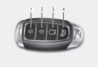
Your HYUNDAI uses a Smart Key, which you can use to lock or unlock the driver
and passenger doors or the rear liftgate.
1. Door Lock
2. Door Unlock
3. Remote start
read more


 Shift Cable. Components and components location
