Hyundai Venue: Automatic Transaxle System / Specifications
Hyundai Venue (QX) (2020-2025) Service Manual / Automatic Transaxle System / Specifications
| Specifications |
|
Item |
Specifications |
||
|
Transaxle type |
A6GF1 - 2 |
||
|
Engine type |
Gasoline 1.6MPI |
||
|
Torque converter type |
3 - element, 1 - stage, 2 - phase type |
||
|
Torque converter size |
Ø236 mm (9.2913 in) |
||
|
Oil pump system |
Mechanical internal gear pump |
||
|
Friction elements |
Clutch : 2EA |
||
|
Brake : 3EA |
|||
|
OWC : 1EA |
|||
|
Planetary gear |
3EA |
||
|
Gear ratio |
1st |
4.400 |
|
|
2nd |
2.726 |
||
|
3rd |
1.834 |
||
|
4th |
1.392 |
||
|
5th |
1.000 |
||
|
6th |
0.774 |
||
|
Reverse |
3.440 |
||
|
Final gear ratio |
Nomal |
Tire 15 in. |
6.052 |
|
Tire 17 in. |
6.483 |
||
|
High mountain |
Tire 15 in. |
6.483 |
|
|
Tire 17 in. |
6.483 |
||
|
Low octain |
Tire 15 in. |
6.483 |
|
|
Tire 17 in. |
6.483 |
||
|
Fluid pressure balance piston |
2EA |
||
|
Accumulator |
4EA |
||
|
Solenoid valve |
7EA (VFS : 6EA, ON / OFF : 1EA) |
||
|
Shift lever position |
4 Range (P, R, N, D) |
||
|
Oil filter |
1EA |
||
VFS : Variable Force Solenoid
▶ Sensors
Input Speed Sensor
▷ Type : Hall effect sensor
▷ Specifications
|
Items |
Specifications |
|
|
Operation condition (°C)°F |
(-40 to 150) -40 to 302 |
|
|
Output voltage (V) |
High |
1.18 - 1.68 |
|
Low |
0.59 - 0.84 |
|
Output Speed Sensor
▷ Type : Hall effect sensor
▷ Specifications
|
Items |
Specifications |
|
|
Operation condition (°C)°F |
(-40 to 150) -40 to 302 |
|
|
Output voltage (V) |
High |
1.18 - 1.68 |
|
Low |
0.59 - 0.84 |
|
Oil Temperature Sensor
▷ Type : Negative Thermal Coefficient (NTC)
▷ Specifications
|
Temp.[(°C)°F] |
Resistance (Ω) |
Min |
Max |
|
(-40) -40 |
48153 |
45301 |
51006 |
|
(-20) -4.0 |
15614 |
14785 |
16443 |
|
(0) 32.0 |
5887 |
5605 |
6168 |
|
(20) 68.0 |
2510.6 |
2401.9 |
2619.3 |
|
(40) 104.0 |
1199.6 |
1152.4 |
1246.7 |
|
(60) 140.0 |
612.3 |
590.3 |
634.2 |
|
(80) 176.0 |
329.5 |
318.7 |
340.3 |
|
(100) 212.0 |
186 |
180.4 |
191.6 |
|
(120) 248.0 |
109.7 |
106.1 |
113.2 |
|
(140) 284.0 |
67.16 |
64.82 |
69.5 |
|
(150) 302.0 |
53.24 |
51.32 |
55.16 |
▶ Inhibitor Switch
▷ Type : Combination of output signals from 4 terminals
▷ Specifications
|
Items |
Specifications |
|
Power supply (V) |
12 |
|
Output type |
Combination of output signals |
▶ Solenoid Valves
ON / OFF Solenoid Valve (SS - A)
▷ Control type : Normally low type
|
Shape |
Items |
Specifications |
|
|
Control current (voltage) [mA] |
9 - 16 |
|
Supply pressure [kpa (kgf / cm², psi)] |
490.33 (5.0, 71.12) |
|
|
Control pressure [kpa (kgf / cm², psi)] |
0 - 490.33 (0 - 5.0, 0 - 71.12) |
|
| Internal
resistance (Ω) |
10 - 11 |
Clutch / Brake control VFS [T / CON]
▷ Control type : Normally low type
|
Shape |
Items |
Specifications |
|
|
Control current(voltage) [mA] |
0 - 850 |
|
Supply pressure [kpa (kgf/cm², psi)] |
539.36 (5.5, 78.23) |
|
|
Control pressure [kpa (kgf/cm², psi)] |
0 - 519.75 (0 - 5.3, 0 - 75.38) |
|
| Internal
resistance(Ω) |
4.8 - 5.4 |
Line Pressure Control VFS[Line pressure]
▷ Control type : Normally high type
|
Shape |
Items |
Specifications |
|
|
Control current(voltage) [mA] |
0 - 850 |
|
Supply pressure [kpa (kgf/cm², psi)] |
539.36 (5.5, 78.23) |
|
|
Control pressure [kpa (kgf/cm², psi)] |
0 - 519.75 (0 - 5.3, 0 - 75.38) |
|
| Internal
resistance(Ω) |
4.8 - 5.4 |
Clutch/Brake control VFS[26/B,35R/C]
▷ Control type : Normally low type
|
Shape |
Items |
Specifications |
|
|
Control current(voltage) [mA] |
0 - 1100 |
|
Supply pressure [kpa (kgf/cm², psi)] |
1569.06 (16, 227.57) |
|
|
Control pressure [kpa (kgf/cm², psi)] |
0 - 1569.06 (0 - 16, 0 - 227.57) |
|
| Internal
resistance(Ω) |
5.0 - 5.6 |
Clutch/Brake control VFS[UD/B, OD/C]
▷ Control Type : Normally high type
|
Shape |
Items |
Specifications |
|
|
Control current(voltage) [mA] |
0 - 1100 |
|
Supply pressure [kpa (kgf/cm², psi)] |
1569.06 (16, 227.57) |
|
|
Control pressure [kpa (kgf/cm², psi)] |
0 - 1569.06 (0 - 16, 0 - 227.57) |
|
| Internal
resistance(Ω) |
5.0 - 5.6 |
▶ Solenoid Valve Operation Table
|
|
UD |
OD & LR |
35 R |
26 |
SS - A |
|
P |
● |
|
|
|
● |
|
N |
● |
|
|
|
● |
|
1 st |
|
Δ |
|
|
Δ |
|
2 nd |
|
● |
|
● |
|
|
3 rd |
|
● |
● |
|
|
|
4 th |
|
|
|
|
|
|
5 th |
● |
|
● |
|
|
|
6 th |
● |
|
|
● |
|
|
REV |
● |
|
● |
|
● |
● : Connected status
Δ : Connected at vehicle speed above 8km/h
▶ Tightening Torques
|
Item |
N.m
|
kgf.m
|
lb-ft
|
|
Shift cable bracket mounting bolt |
14.7 - 21.6 |
1.5 - 2.2 |
10.8 - 15.9 |
|
Fixing nut of shift cable in the manual lever |
9.8 - 13.7 |
1.0 - 1.4 |
7.2 - 10.1 |
|
Automatic transaxle upper mounting bolt (TM=>Eng) |
42.2 - 53.9 |
4.3 - 5.5 |
31.1 - 39.8 |
|
Automatic transaxle mounting bracket bolt |
88.3 - 107.9 |
9.0 - 11.0 |
65.1 - 79.6 |
|
Automatic transaxle support bracket mounting bolt |
58.9 - 78.5 |
6.0 - 8.0 |
43.4 - 57.8 |
|
Torque converter mounting bolt |
45.1 - 52.0 |
4.6 - 5.3 |
33.3 - 38.3 |
|
Automatic transaxle lower mounting bolt (Eng=>TM) |
42.2 - 48.1 |
4.3 - 4.9 |
31.1 - 35.4 |
|
42.2 - 53.9 |
4.3 - 5.5 |
31.1 - 39.8 |
|
|
TCM mounting nut |
9.8 - 11.8 |
1.0 - 1.2 |
7.2 - 8.7 |
|
Input shaft speed sensor mounting bolt |
9.8 - 11.8 |
1.0 - 1.2 |
7.2 - 8.7 |
|
Output shaft speed sensor mounting bolt |
9.8 - 11.8 |
1.0 - 1.2 |
7.2 - 8.7 |
|
Shift lever assembly bolt |
8.8 - 13.7 |
0.9 - 1.4 |
9.4 - 10.1 |
|
Inhibitor switch mounting bolt |
9.8 - 11.8 |
1.0 - 1.2 |
7.2 - 8.7 |
|
Valve body cover mounting bolt |
11.8 - 13.7 |
1.2 - 1.4 |
8.7 - 10.1 |
|
ATF drain plug |
33.3 - 43.1 |
3.4 - 4.4 |
24.6 - 31.8 |
|
Starter mounting bolt |
49.0 - 63.7 |
5.0 - 6.5 |
36.2 - 47.0 |
| Lubricants |
▶ Fluid
|
ATF Grade |
Recommended |
Allowed |
|
ATF SP-Ⅳ |
SK ATF SP-Ⅳ, MICHANG ATF SP-Ⅳ,NOCA ATF SP-Ⅳ, Hyundai Genuine ATF SP-Ⅳ |
|
|
ATF Quantity |
6.7L(1.77 U.S gal., 7.08 U.S.qt., 5.90 Imp.qt.) |
|
▶ Sealant
|
Item |
Specified
sealant |
|
Torque converter housing |
LOCTITE FMD-546 |

 Special service tools
Special Service Tools
Tools
(Number and name)
Illustration
Use
09200-3N000
Engine support fixture (Beam)
Removal and installation of the transaxle...
Other information:
Hyundai Venue (QX) (2020-2025) Owners Manual: System Maintenance
Cabin air filter [A] : Outside air, [B] : Recirculated air [C] : Cabin air filter, [D] : Blower [E] : Evaporator core, [F] : Heater core The cabin air filter is installed behind the glove box. It filters the dust or other pollutants that enter the vehicle through the heating and air conditioning system...
Hyundai Venue (QX) (2020-2025) Service Manual: Height Adjust. Repair procedures
Replacement 1. Remove the front seat belt upper anchor. (Refer to Front Seat Belt - "Front Seat Belt Pretensioner") 2. After loosening the mounting bolts, then remove the height adjust (A)...
Categories
- Manuals Home
- 1st Generation Venue Owners Manual
- 1st Generation Venue Service Manual
- Electronic Stability Control (ESC)
- Warning and Indicator Lights
- Theft-Alarm System
- New on site
- Most important about car
Remote Key
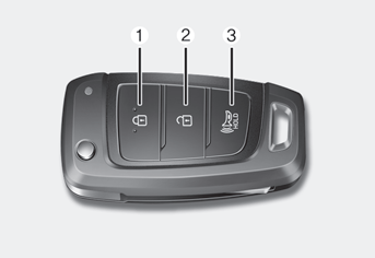
Your HYUNDAI uses a remote key, which you can use to lock or unlock the driver and passenger doors or the rear liftgate.
(1) Door Lock
(2) Door Unlock
(3) Panic
Locking Your Vehicle
To lock your vehicle:
1. Make sure all doors, the engine hood and the liftgate are closed.

Copyright © 2025 www.hvenueqx.com