Hyundai Venue: ESP(Electronic Stability Program) System / Front Wheel Speed Sensor. Repair procedures

Hyundai Venue (QX) (2020-2024) Service Manual / Brake System / ESP(Electronic Stability Program) System / Front Wheel Speed Sensor. Repair procedures

Removal
1.
Loosen the wheel nuts slightly.
Raise the vehicle, and make sure it is securely supported.
2.
Remove the front wheel and tire (A) from front hub.
Tightening torque :
107.9 - 127.5 N.m (11.0 - 13.0 kgf.m, 79.6 - 94.0 lb-ft)
Hyundai Venue. Front Wheel Speed Sensor. Repair procedures   
Be careful not to damage the hub bolts when removing the front wheel and tire (A).

Hyundai Venue. Front Wheel Speed Sensor. Repair procedures

3.
Remove the front wheel guard.
(Refer to Body - "Front Wheel Guard")
4.
Disconnect the front wheel speed sensor connector (A) and then remove the fixing clip (B).

Hyundai Venue. Front Wheel Speed Sensor. Repair procedures

5.
Remove the wheel speed sensor bracket bolt (A).
Tightening torque :
7.8 - 11.8 N.m (0.8 - 1.2 kgf.m, 5.8 - 8.7 lb-ft)

Hyundai Venue. Front Wheel Speed Sensor. Repair procedures

6.
Remove the wheel speed sensor bracket bolt (A).
Tightening torque :
8.8 - 13.7 N.m (0.9 - 1.4 kgf.m, 6.5 - 10.1 lb-ft)

Hyundai Venue. Front Wheel Speed Sensor. Repair procedures

7.
Loosen the bolt and then disconnect the front wheel speed sensor (A).
Tightening torque :
7.8 - 11.8 N.m (0.8 - 1.2 kgf.m, 5.8 - 8.7 lb-ft)

Hyundai Venue. Front Wheel Speed Sensor. Repair procedures

Installation
1.
To install, reverse the removal procedure.
Inspection
1.
Measure the output voltage between the terminal of the wheel speed sensor and the body ground.
Hyundai Venue. Front Wheel Speed Sensor. Repair procedures   
In order to protect the wheel speed sensor, when measuring output voltage, a 120Ω resister must be used as shown.

Hyundai Venue. Front Wheel Speed Sensor. Repair procedures

2.
Compare the change of the output voltage of the wheel speed sensor to the normal change of the output voltage as shown below.

Hyundai Venue. Front Wheel Speed Sensor. Repair procedures

V_Low : 0.7V - 1.0V
V_High : 1.4V - 2.0V
Frequency range : 1 - 2,500 Hz

    Front Wheel Speed Sensor. Components and components location

    ..

    Rear Wheel Speed Sensor. Components and components location

    ..

    Other information:

    Hyundai Venue (QX) (2020-2024) Service Manual: Engine Control Module (ECM). Schematic diagrams


    Engine Control Module (ECM) [M/T] ECM Terminal Function [M/T] Connector [A] Pin No Description Connected to 1 Injector (Cylinder #1) control output Injector (Cylinder #1) 2 Sensor power (+5V) Throttle Position Sensor (TPS) # 1, 2 [ETC module] 3 Sensor power (+5V) Accelerator Position Sensor (APS) 1 4 Main Relay control output Main Relay 5 - - 6 Alternator signal input [FR] Alternator 7 Engine coolant temperature sensor (ECTS) signal input Engine coolant temperature sensor (ECTS) 8 Sensor ground Manifold absolute pressure sensor (MAPS) 9 - 10 Sensor ground Heated Oxygen Sensor (HO2S) [Bank 1 / Sensor 2] 11 - 12 - 13 CVVT Oil Control (OCV) Valve [Bank 1/Intake] control output CVVT Oil Control Valve (OCV) [Bank 1 / Intake] 14 Sensor power (+5V) Manifold absolute pressure sensor (MAPS) 15 Sensor power (+5V) Accelerator Position Sensor (APS) #2 A/C Pressure Transducer (APT) 16 Sensor power (+5V) CMPS [Bank 1 / Intake] CMPS [Bank 1 / Exhaust] 17 Vehicle speed signal input ABS/ESP Control Module [With ABS / ESP] 18 Battery voltage supply after ignition switch Ignition Switch 19 Sensor ground Camshaft Position Sensor (CMPS) [Bank 1 / Exhaust] 20 Sensor ground A/C Pressure Transducer (APT) 21 Sensor ground Battery sensor 22 - 23 - 24 - 25 Injector (Cylinder #2) control output Injector (Cylinder #2) 26 Cooling Fan Relay [High] control output Cooling Fan Relay [High] 27 Start relay control output (With smart key) Start relay 28 Alternator control output [COM] Alternator 29 C-CAN [Low] Other control module, Data Link Connector (DLC), 30 - 31 Camshaft Position Sensor (CMPS) [Bank 1 / Exhaust] signal input Camshaft Position Sensor (CMPS) [Bank 1 / Exhaust] 32 Sensor ground Crankshaft Position Sensor (CKPS) 33 Crankshaft Position Sensor (CKPS) signal input Crankshaft Position Sensor (CKPS) 34 Sensor ground Throttle Position Sensor (TPS) 1, 2 35 Sensor ground Accelerator Position Sensor (APS) 2 36 Sensor ground Accelerator Position Sensor (APS) 1 37 Injector (Cylinder #4) control output Injector (Cylinder #4) 38 - 39 Engine RPM signal output Smart key Control Module 40 Immobilizer communication line Immobilizer Control module [Without Smart Key] Smart Key Control module [With Smart Key] 41 C-CAN [High] Other control module, Data Link Connector (DLC) 42 - 43 Purge Control Solenoid Valve control output Purge Control Solenoid Valve (PCSV) 44 - 45 Injector (Cylinder #3) control output Injector (Cylinder #3) 46 Cooling Fan Relay [Low] control output Cooling Fan Relay [Low] 47 Camshaft Position Sensor (CMPS) [Bank 1 / Intake] signal input haft Position Sensor (CMPS) [Bank 1 / Intake] 48 Battery power (B+) Battery 49 Heated Oxygen Sensor [Bank 1 / Sensor 1] Heater control output Heated Oxygen Sensor [Bank 1 / Sensor 1] 50 Power Ground Chassis Ground 51 - 52 Power Ground Chassis Ground 53 Heated Oxygen Sensor [Bank 1 / Sensor 2] Heater control output Heated Oxygen Sensor [Bank 1 / Sensor 2] 54 CVVT Oil Control (OCV) Valve [Bank 1 / Exhaust] control output CVVT Oil Control Valve (OCV) [Bank 1 / Exhaust] 55 Battery voltage supply after main relay Main relay 56 Battery voltage supply after main relay Main relay Connector [B] Pin No Description Connected to 1 Sensor ground Engine Coolant Temperature Sensor (ECTS) 2 Throttle position sensor (TPS) #2 signal input Throttle position sensor (TPS) #2 [ETC Module] 3 Manifold absolute pressure sensor (MAPS) signal input Manifold absolute pressure sensor (MAPS) 4 A/C Pressure Transducer (APT) signal input A/C Pressure Transducer (APT) 5 - 6 - 7 Accelerator Position Sensor (APS) #1 signal input Accelerator Position Sensor (APS) #1 8 - 9 - 10 - 11 Electric Load signal input (Defrost) A/C Control Module, Outside Mirror 12 Brake switch 1 signal input Brake lamp swtich , Brake switch 13 Heated Oxygen Sensor [Bank 1 / Sensor 2] signal input Heated Oxygen Sensor [Bank 1 / Sensor 2] 14 Battery Sensor Temperature signal input Battery sensor 15 Intake air temperature sensor (IATS) signal input Intake Air temperature sensor (IATS) 16 Battery Sensor Current Direct signal input Battery sensor 17 - 18 Accelerator Position Sensor (APS) #2 signal input Accelerator Position Sensor (APS) #2 19 - 20 - 21 - 22 Throttle position sensor (TPS) #1 signal input Throttle position sensor (TPS) #1 23 Brake Lamp Switch signal input Brake Switch 24 Start switch signal input Ignition switch 25 Sensor ground Heated Oxygen Sensor [Bank 1 / Sensor 1] 26 - 27 Sensor ground Knock sensor (KS) 28 - 29 Wheel speed sensor [B] signal input Front wheel speed sensor (RH) [Without ABS] 30 Wheel speed sensor [A] signal input Front wheel speed sensor (RH) [Without ABS] 31 - 32 Sensor ground Camshaft Position Sensor (CMPS) [Bank 1 / Intake] Camshaft Position Sensor (CMPS) [Bank 1 / Exhaust] 33 Power Ground Chassis Ground 34 Clutch Switch signal input Clutch switch [M...

    Hyundai Venue (QX) (2020-2024) Owners Manual: Intelligent Variable Transmission (IVT)


    ..

    Categories

    Head Restraints

    The vehicle’s front and rear seats have adjustable head restraints. The head restraints provide comfort for passengers, but more importantly they are designed to help protect passengers from whiplash and other neck and spinal injuries during an accident, especially in a rear impact collision.

    WARNING

    To reduce the risk of serious injury or death in an accident, take the following precautions when adjusting your head restraints:

    Always properly adjust the head restraints for all passengers BEFORE starting the vehicle. NEVER let anyone ride in a seat with the head restraints removed or reversed.
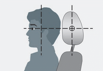
    Hyundai Venue. Head Restraints

    read more


    Copyright © 2024 www.hvenueqx.com