Hyundai Venue: Manual Transaxle System / Manual Transaxle Fluid. General information

Hyundai Venue (QX) (2020-2025) Service Manual / Manual Transaxle System / Manual Transaxle System / Manual Transaxle Fluid. General information

General Information
1.
Check & Change intervals
 Check & Replenishment
Change
Capacity
Oil specification
Normal use
Severe Use
60,000 km / 4 years
(40,000 miles / 4years)
No service required
120,000 km
(80,000 miles)
1.5 - 1.6 L
(0.40 -0.42 U.S.gal., 1.58 - 1.69 U.S.qt., 1.32- 1.40 lmp qt.)
API Service GL-4, SAE 70W
Recommended oil
SHELL : SPIRAX S6 GHME 70W MTF
SK : HK SYN MTF 70W
GS CALTEX : GS MTF HD 70W

Hyundai Venue. Manual Transaxle Fluid. General information   
Severe usage is defined as
Frequent driving on rough (Bumpy road, gravel road, snowy road, unpaved road. etc .).
Frequent driving on mountain road, ascent/descent
Driving for patrol, taxi, commercial car or vehicle towing.
Frequent driving under high speed (Over 170km) driving condition.
More than 50% driving in heavy city traffic during hot weather above 30°C (90°F)
Driving in areas using salt or other corrosive materials or in very cold weather.
Towing a trailer or using a camper on roof rack.

    Repair procedures

    Removal 1. Turn OFF ignition switch and disconnect the negative (-) battery cable. 2. Remove the air cleaner and air duct...

    Back-up Lamp Switch. Description and operation

    ..

    Other information:

    Hyundai Venue (QX) (2020-2025) Service Manual: Engine Control Module (ECM). Schematic diagrams


    Engine Control Module (ECM) [M/T] ECM Terminal Function [M/T] Connector [A] Pin No Description Connected to 1 Injector (Cylinder #1) control output Injector (Cylinder #1) 2 Sensor power (+5V) Throttle Position Sensor (TPS) # 1, 2 [ETC module] 3 Sensor power (+5V) Accelerator Position Sensor (APS) 1 4 Main Relay control output Main Relay 5 - - 6 Alternator signal input [FR] Alternator 7 Engine coolant temperature sensor (ECTS) signal input Engine coolant temperature sensor (ECTS) 8 Sensor ground Manifold absolute pressure sensor (MAPS) 9 - 10 Sensor ground Heated Oxygen Sensor (HO2S) [Bank 1 / Sensor 2] 11 - 12 - 13 CVVT Oil Control (OCV) Valve [Bank 1/Intake] control output CVVT Oil Control Valve (OCV) [Bank 1 / Intake] 14 Sensor power (+5V) Manifold absolute pressure sensor (MAPS) 15 Sensor power (+5V) Accelerator Position Sensor (APS) #2 A/C Pressure Transducer (APT) 16 Sensor power (+5V) CMPS [Bank 1 / Intake] CMPS [Bank 1 / Exhaust] 17 Vehicle speed signal input ABS/ESP Control Module [With ABS / ESP] 18 Battery voltage supply after ignition switch Ignition Switch 19 Sensor ground Camshaft Position Sensor (CMPS) [Bank 1 / Exhaust] 20 Sensor ground A/C Pressure Transducer (APT) 21 Sensor ground Battery sensor 22 - 23 - 24 - 25 Injector (Cylinder #2) control output Injector (Cylinder #2) 26 Cooling Fan Relay [High] control output Cooling Fan Relay [High] 27 Start relay control output (With smart key) Start relay 28 Alternator control output [COM] Alternator 29 C-CAN [Low] Other control module, Data Link Connector (DLC), 30 - 31 Camshaft Position Sensor (CMPS) [Bank 1 / Exhaust] signal input Camshaft Position Sensor (CMPS) [Bank 1 / Exhaust] 32 Sensor ground Crankshaft Position Sensor (CKPS) 33 Crankshaft Position Sensor (CKPS) signal input Crankshaft Position Sensor (CKPS) 34 Sensor ground Throttle Position Sensor (TPS) 1, 2 35 Sensor ground Accelerator Position Sensor (APS) 2 36 Sensor ground Accelerator Position Sensor (APS) 1 37 Injector (Cylinder #4) control output Injector (Cylinder #4) 38 - 39 Engine RPM signal output Smart key Control Module 40 Immobilizer communication line Immobilizer Control module [Without Smart Key] Smart Key Control module [With Smart Key] 41 C-CAN [High] Other control module, Data Link Connector (DLC) 42 - 43 Purge Control Solenoid Valve control output Purge Control Solenoid Valve (PCSV) 44 - 45 Injector (Cylinder #3) control output Injector (Cylinder #3) 46 Cooling Fan Relay [Low] control output Cooling Fan Relay [Low] 47 Camshaft Position Sensor (CMPS) [Bank 1 / Intake] signal input haft Position Sensor (CMPS) [Bank 1 / Intake] 48 Battery power (B+) Battery 49 Heated Oxygen Sensor [Bank 1 / Sensor 1] Heater control output Heated Oxygen Sensor [Bank 1 / Sensor 1] 50 Power Ground Chassis Ground 51 - 52 Power Ground Chassis Ground 53 Heated Oxygen Sensor [Bank 1 / Sensor 2] Heater control output Heated Oxygen Sensor [Bank 1 / Sensor 2] 54 CVVT Oil Control (OCV) Valve [Bank 1 / Exhaust] control output CVVT Oil Control Valve (OCV) [Bank 1 / Exhaust] 55 Battery voltage supply after main relay Main relay 56 Battery voltage supply after main relay Main relay Connector [B] Pin No Description Connected to 1 Sensor ground Engine Coolant Temperature Sensor (ECTS) 2 Throttle position sensor (TPS) #2 signal input Throttle position sensor (TPS) #2 [ETC Module] 3 Manifold absolute pressure sensor (MAPS) signal input Manifold absolute pressure sensor (MAPS) 4 A/C Pressure Transducer (APT) signal input A/C Pressure Transducer (APT) 5 - 6 - 7 Accelerator Position Sensor (APS) #1 signal input Accelerator Position Sensor (APS) #1 8 - 9 - 10 - 11 Electric Load signal input (Defrost) A/C Control Module, Outside Mirror 12 Brake switch 1 signal input Brake lamp swtich , Brake switch 13 Heated Oxygen Sensor [Bank 1 / Sensor 2] signal input Heated Oxygen Sensor [Bank 1 / Sensor 2] 14 Battery Sensor Temperature signal input Battery sensor 15 Intake air temperature sensor (IATS) signal input Intake Air temperature sensor (IATS) 16 Battery Sensor Current Direct signal input Battery sensor 17 - 18 Accelerator Position Sensor (APS) #2 signal input Accelerator Position Sensor (APS) #2 19 - 20 - 21 - 22 Throttle position sensor (TPS) #1 signal input Throttle position sensor (TPS) #1 23 Brake Lamp Switch signal input Brake Switch 24 Start switch signal input Ignition switch 25 Sensor ground Heated Oxygen Sensor [Bank 1 / Sensor 1] 26 - 27 Sensor ground Knock sensor (KS) 28 - 29 Wheel speed sensor [B] signal input Front wheel speed sensor (RH) [Without ABS] 30 Wheel speed sensor [A] signal input Front wheel speed sensor (RH) [Without ABS] 31 - 32 Sensor ground Camshaft Position Sensor (CMPS) [Bank 1 / Intake] Camshaft Position Sensor (CMPS) [Bank 1 / Exhaust] 33 Power Ground Chassis Ground 34 Clutch Switch signal input Clutch switch [M...

    Hyundai Venue (QX) (2020-2025) Service Manual: Door Scuff Trim. Repair procedures


    Replacement [Front]    • Put on gloves to prevent hand injuries. • When removing with a flat-tip screwdriver or remover, wrap protective tape around the tools to prevent damage to components...

    Categories

    Fuel gauge

    Hyundai Venue. Fuel gauge

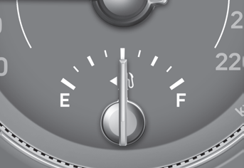
    This gauge indicates the approximate amount of fuel remaining in the fuel tank.

    Information

    The fuel tank capacity is given in chapter 2. The fuel gauge is supplemented by a low fuel warning light, which will illuminate when the fuel tank is nearly empty. On inclines or curves, the fuel gauge pointer may fluctuate or the low fuel warning light may come on earlier than usual due to the movement of fuel in the tank.

    read more


    Copyright © 2025 www.hvenueqx.com