Hyundai Venue: Timing System / Drive Belt. Repair procedures
Hyundai Venue (QX) (2020-2025) Service Manual / Engine Mechanical System / Timing System / Drive Belt. Repair procedures
| Removal |
| 1. |
Disconnect the battery negative terminal.
|
| 2. |
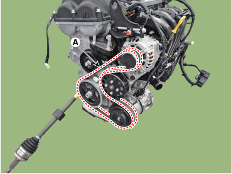
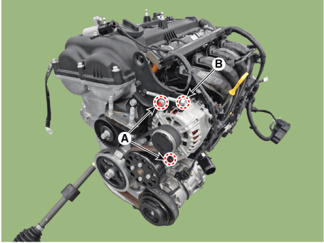
Loosen the mounting bolts (A) and then, turn the adjusting bolt (B)
clockwise in loose tension.
|

| 3. |
Remove the drive belt (A).
|
| Inspection |
Drive Belt Inspection
| 1. |
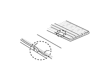
Visually check the belt for excessive wear, frayed cords etc.
If any defect has been found, replace the drive belt.
|

| 2. |
Measure the drive belt tension. if necessary, drive belt an adjust.
|
| Adjustment |
Drive belt tension measurement and adjustment
| Belt tension measurement |
Measure the belt tension using a mechanical tension gauge or a sonic tension
meter.
|
Tension
New Belt :
961.0 - 980.7 N.m (98.0 - 100.0 kgf.m, 216.1 - 220.5 lb-ft)
Used Belt :
637.4 - 735.5 N.m (65.0 - 75.0 kgf.m, 143.3 - 165.3 lb-ft)
|
|

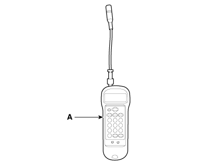
| Using a mechanical tension gauge (BT-33-73F, BTG-2 type) |
| 1. |
While pressing the handle (A) of the gauge, insert the belt (B) between
pulley and pulley (or idler) into the gap between spindle (C) and hook
(D).
|
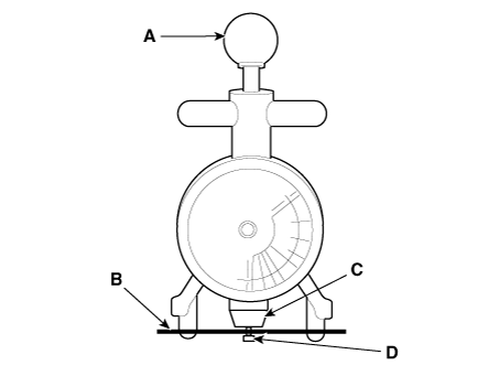
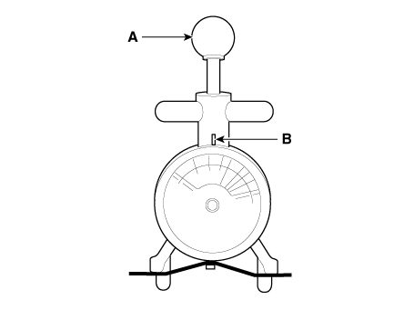
| 2. |
After releasing the handle (A), read a value on the dial pointed by
the indicator (B).
|
| Using a sonic tension meter (U-505/507 type) |
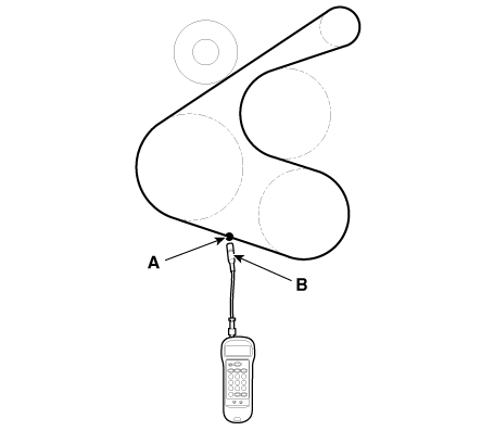
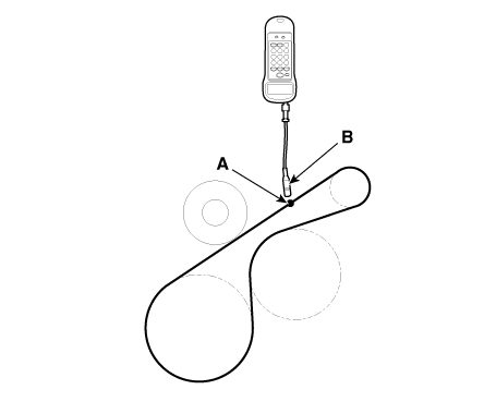
| 3. |
Input the belt specifications into the tension meter.
|
||||||||||||||||||||||||||||

| 4. |
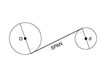
Locate the micro phone (B) close to the center of belt span (A) and
bounce the belt by finger 2-3 times. Read a value on the display.
[With A/C]
[Without A/C]
|
| If adjustment is necessary |
| 5. |
Loosen the mounting bolts (A).
|
| 6. |
Tighten the adjusting bolt (B) clockwise in loose tension ; loosen the
bolt counterclockwise in high tension.
|

| 7. |
Recheck tension of the belt.
|
| 8. |
After adjusting tension, tighten the through bolts.
|
| Installation |
| 1. |
Install the drive belt (A).
|
| 2. |
Adjust tension by tightening the alternator tension adjust bolt (B)
and then install the mounting bilts (A).
|
| 3. |
Connect the battery negative terminal.
|


Other information:
Hyundai Venue (QX) (2020-2025) Service Manual: USB jack. Description and operation
Description The multimedia jack on the console upper cover is for customers who like to listen to external portable music players like the MP3 etc., through the vehicle's sound system when it is linked to this jack. The customer has this added option...
Hyundai Venue (QX) (2020-2025) Service Manual: Schematic diagrams
..
Categories
- Manuals Home
- 1st Generation Venue Owners Manual
- 1st Generation Venue Service Manual
- Warning and Indicator Lights
- System Setting and Activation
- Type B, C
- New on site
- Most important about car
Interior Overview
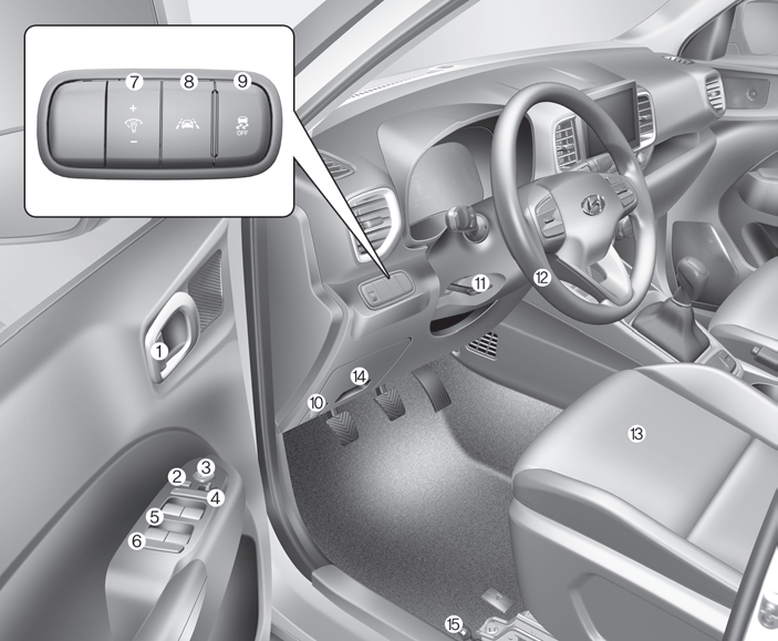
1. Door lock/unlock button
2. Outside rearview mirror control switch
3. Central door lock switch
4. Power window switches
5. Power window lock switch

Copyright © 2025 www.hvenueqx.com