Hyundai Venue: Smart Key System / Smart Key Diagnostic. Repair procedures
Hyundai Venue (QX) (2020-2025) Service Manual / Body Electrical System / Smart Key System / Smart Key Diagnostic. Repair procedures
| Inspection |
Self Diagnosis With Scan Tool
It will be able to diagnose defects of SMART KEY system with GDS quickly. GDS
can operates actuator forcefully, input/output value monitoring and self diagnosis.
The following three features will be major problem in SMART KEY system.
| 1. |
Problem in SMART KEY unit input.
|
| 2. |
Problem in SMART KEY unit.
|
| 3. |
Problem in SMART KEY unit output.
|
So the following three diagnosis operates will be the major problem solution
process.
| 4. |
SMART KEY unit Input problem : switch diagnosis
|
| 5. |
SMART KEY unit problem : communication diagnosis
|
| 6. |
SMART KEY unit Output problem : antenna and switch output diagnosis
|
Switch Diagnosis
| 1. |
In the body electrical system, failure can be quickly diagnosed by using
the vehicle diagnostic system (GDS).
The diagnostic system(GDS) provides the following information.
|
| 2. |
If diagnose the vehicle by GDS, select "DTC Analysis" and "Vehicle".
|
| 3. |
If check current status, select the "Data Analysis" and "Car model".
|
| 4. |
Select the SMK' to be checked in order to check the vehicle with the
tester.
|
| 5. |
You can see the situation of each switch on scanner after connecting
the "current data" process.
|
Fault Code Searching
| 1. |
Fault code searching that the each linked components operates normal.
|
| 2. |
Connect the cable of GDS to the data link connector in driver side crash
pad lower panel.
|
| 3. |
Select the 'Fault Code Searching' and 'Car model'.
|
Antenna Actuation Diagnosis
| 1. |
Connect the cable of GDS to the data link connector in driver side crash
pad lower panel.
|
| 2. |
Select the 'Actuation Test' and 'Car model'.
|
| 3. |
Set the smart key near the related antenna and operate it with a GDS.
|
| 4. |
Set the smart key near the related antenna and operate it with a GDS.
|
| 5. |
If the LED of smart key is blinking, the smart key is normal.
|
| 6. |
If the LED of smart key is not blinking, check the voltage of smart
key battery.
|
| 7. |
Antenna actuation
|
Antenna Status Check
| 1. |
Connect the cable of GDS to the data link connector in driver side crash
pad lower panel.
|
| 2. |
Select the 'S/W Management' and 'Car model'.
|

| 3. |
Select the 'Smart Key Unit' and 'Antenna Status Check'.
|
| 4. |
Set the smart key near the related antenna and operate it with a GDS.
|
| 5. |
If the smart key runs normal , the related antenna, smart key(transmission,
reception) and exterior receiver are normal.
|
| 6. |
Antenna status
|
FOB Status Check
| 1. |
Connect the cable of GDS to the data link connector in driver side crash
pad lower panel.
|
| 2. |
Select the 'S/W Management' and 'Car model'.
|

| 3. |
Select the 'Smart Key Unit' and 'FOB KEY STATUS IMFORMATION'.
|

Smart Key Status Check
| 1. |
Connect the cable of GDS to the data link connector in driver side crash
pad lower panel.
|
| 2. |
Select the 'S/W Management' and 'Car model'.
|

| 3. |
Select the 'Smart Key Unit' and 'SMK STATUS INFORMATION'.
|

Neutralization Status Check
| 1. |
Connect the cable of GDS to the data link connector in driver side crash
pad lower panel.
|
| 2. |
Select the 'S/W Management' and 'Car model'.
|
| 3. |
Select the 'Smart Key Unit' and 'Neutralization Mode'.
|


Other information:
Hyundai Venue (QX) (2020-2025) Service Manual: Injector. Schematic diagrams
..
Hyundai Venue (QX) (2020-2025) Owners Manual: Exterior Overview
Front view 1. Hood 2. Headlamp/Daytime running lamp 3. Turn signal lamp 4. Tires and wheels 5. Outside rearview mirror 6. Front windshield wiper blades 7. Windows Rear view 1. Antenna 2. Doors 3. Fuel filler door 4. High mounted stop lamp 5...
Categories
- Manuals Home
- 1st Generation Venue Owners Manual
- 1st Generation Venue Service Manual
- Lighting control
- Trip Computer
- Liftgate
- New on site
- Most important about car
Air bag collision sensors
WARNING
To reduce the risk of an air bag deploying unexpectedly and causing serious injury or death:
Do not hit or allow any objects to impact the locations where air bags or sensors are installed. Do not perform maintenance on or around the air bag sensors. If the location or angle of the sensors is altered, the air bags may deploy when they should not or may not deploy when they should. Do not install bumper guards or replace the bumper with a nongenuine HYUNDAI parts. This may adversely affect the collision and air bag deployment performance. Place the ignition switch in the LOCK/OFF or ACC position when the vehicle is being towed to prevent inadvertent air bag deployment. Have all air bag repairs conducted by an authorized HYUNDAI dealer.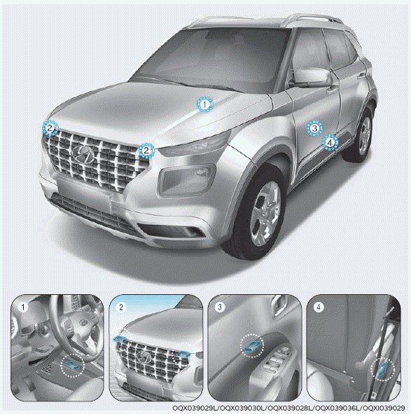

Copyright © 2025 www.hvenueqx.com