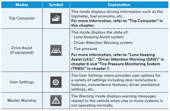
Hyundai Venue: LCD Display / LCD Display Modes

Shift to P to edit settings
This warning message appears if you try to adjust the User Settings while driving.
For your safety, change the User Settings after parking the vehicle, applying
the parking brake and moving the shift lever to P (Park).
Quick guide help
This mode provides quick guides for the systems in the User Settings mode. Select
an item, press and hold the OK button.
Trip computer mode
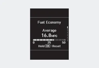
The trip computer mode displays information related to vehicle driving parameters
including fuel economy, trip meter information and vehicle speed.
Drive assist mode
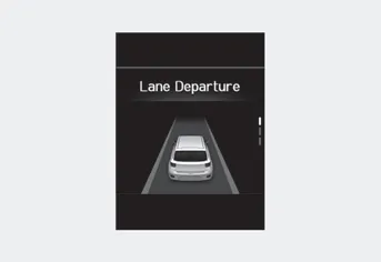
LKA/DAW
This mode displays the state of Lane Keeping Assist system and Driver Attention
Warning system.
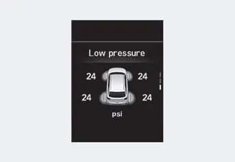
Tire Pressure
This mode displays information related to Tire Pressure.
LCD Display Control
The LCD display modes can be changed by using the control buttons.
1. : MODE button for changing modes
2. : MOVE switch for changing items
3...
This warning light informs the driver the following situations.
-- Forward Collision-Avoidance Assist system malfunction (if equipped)
-- Forward Collision-Avoidance Assist radar blocked (if equipped)
-- Blind-Spot Collision Warning system malfunction (if equipped)
-- Blind-Spot Collision Warning radar blocked (if equipped)
-- Lamp malfunction (if equipped)
-- High Beam Assist malfunction (if equipped)
-- Tire Pressure Monitoring System (TPMS) malfunction (if equipped)
The Master Warning Light illuminates if one or more of the above warning situations
occur...
Other information:
Engine Control Module (ECM)
[M/T]
ECM Terminal Function [M/T]
Connector [A]
Pin No
Description
Connected to
1
Injector (Cylinder #1) control output
Injector (Cylinder #1)
2
Sensor power (+5V)
Throttle Position Sensor (TPS) # 1, 2 [ETC module]
3
Sensor power (+5V)
Accelerator Position Sensor (APS) 1
4
Main Relay control output
Main Relay
5
-
-
6
Alternator signal input [FR]
Alternator
7
Engine coolant temperature sensor (ECTS) signal input
Engine coolant temperature sensor (ECTS)
8
Sensor ground
Manifold absolute pressure sensor (MAPS)
9
-
10
Sensor ground
Heated Oxygen Sensor (HO2S) [Bank 1 / Sensor 2]
11
-
12
-
13
CVVT Oil Control (OCV) Valve [Bank 1/Intake] control output
CVVT Oil Control Valve (OCV) [Bank 1 / Intake]
14
Sensor power (+5V)
Manifold absolute pressure sensor (MAPS)
15
Sensor power (+5V)
Accelerator Position Sensor (APS) #2
A/C Pressure Transducer (APT)
16
Sensor power (+5V)
CMPS [Bank 1 / Intake]
CMPS [Bank 1 / Exhaust]
17
Vehicle speed signal input
ABS/ESP Control Module [With ABS / ESP]
18
Battery voltage supply after ignition switch
Ignition Switch
19
Sensor ground
Camshaft Position Sensor (CMPS) [Bank 1 / Exhaust]
20
Sensor ground
A/C Pressure Transducer (APT)
21
Sensor ground
Battery sensor
22
-
23
-
24
-
25
Injector (Cylinder #2) control output
Injector (Cylinder #2)
26
Cooling Fan Relay [High] control output
Cooling Fan Relay [High]
27
Start relay control output (With smart key)
Start relay
28
Alternator control output [COM]
Alternator
29
C-CAN [Low]
Other control module, Data Link Connector (DLC),
30
-
31
Camshaft Position Sensor (CMPS) [Bank 1 / Exhaust] signal input
Camshaft Position Sensor (CMPS) [Bank 1 / Exhaust]
32
Sensor ground
Crankshaft Position Sensor (CKPS)
33
Crankshaft Position Sensor (CKPS) signal input
Crankshaft Position Sensor (CKPS)
34
Sensor ground
Throttle Position Sensor (TPS) 1, 2
35
Sensor ground
Accelerator Position Sensor (APS) 2
36
Sensor ground
Accelerator Position Sensor (APS) 1
37
Injector (Cylinder #4) control output
Injector (Cylinder #4)
38
-
39
Engine RPM signal output
Smart key Control Module
40
Immobilizer communication line
Immobilizer Control module [Without Smart Key]
Smart Key Control module [With Smart Key]
41
C-CAN [High]
Other control module, Data Link Connector (DLC)
42
-
43
Purge Control Solenoid Valve control output
Purge Control Solenoid Valve (PCSV)
44
-
45
Injector (Cylinder #3) control output
Injector (Cylinder #3)
46
Cooling Fan Relay [Low] control output
Cooling Fan Relay [Low]
47
Camshaft Position Sensor (CMPS) [Bank 1 / Intake] signal input
haft Position Sensor (CMPS) [Bank 1 / Intake]
48
Battery power (B+)
Battery
49
Heated Oxygen Sensor [Bank 1 / Sensor 1] Heater control output
Heated Oxygen Sensor [Bank 1 / Sensor 1]
50
Power Ground
Chassis Ground
51
-
52
Power Ground
Chassis Ground
53
Heated Oxygen Sensor [Bank 1 / Sensor 2] Heater control output
Heated Oxygen Sensor [Bank 1 / Sensor 2]
54
CVVT Oil Control (OCV) Valve [Bank 1 / Exhaust] control output
CVVT Oil Control Valve (OCV) [Bank 1 / Exhaust]
55
Battery voltage supply after main relay
Main relay
56
Battery voltage supply after main relay
Main relay
Connector [B]
Pin No
Description
Connected to
1
Sensor ground
Engine Coolant Temperature Sensor (ECTS)
2
Throttle position sensor (TPS) #2 signal input
Throttle position sensor (TPS) #2 [ETC Module]
3
Manifold absolute pressure sensor (MAPS) signal input
Manifold absolute pressure sensor (MAPS)
4
A/C Pressure Transducer (APT) signal input
A/C Pressure Transducer (APT)
5
-
6
-
7
Accelerator Position Sensor (APS) #1 signal input
Accelerator Position Sensor (APS) #1
8
-
9
-
10
-
11
Electric Load signal input (Defrost)
A/C Control Module, Outside Mirror
12
Brake switch 1 signal input
Brake lamp swtich , Brake switch
13
Heated Oxygen Sensor [Bank 1 / Sensor 2] signal input
Heated Oxygen Sensor [Bank 1 / Sensor 2]
14
Battery Sensor Temperature signal input
Battery sensor
15
Intake air temperature sensor (IATS) signal input
Intake Air temperature sensor (IATS)
16
Battery Sensor Current Direct signal input
Battery sensor
17
-
18
Accelerator Position Sensor (APS) #2 signal input
Accelerator Position Sensor (APS) #2
19
-
20
-
21
-
22
Throttle position sensor (TPS) #1 signal input
Throttle position sensor (TPS) #1
23
Brake Lamp Switch signal input
Brake Switch
24
Start switch signal input
Ignition switch
25
Sensor ground
Heated Oxygen Sensor [Bank 1 / Sensor 1]
26
-
27
Sensor ground
Knock sensor (KS)
28
-
29
Wheel speed sensor [B] signal input
Front wheel speed sensor (RH) [Without ABS]
30
Wheel speed sensor [A] signal input
Front wheel speed sensor (RH) [Without ABS]
31
-
32
Sensor ground
Camshaft Position Sensor (CMPS) [Bank 1 / Intake]
Camshaft Position Sensor (CMPS) [Bank 1 / Exhaust]
33
Power Ground
Chassis Ground
34
Clutch Switch signal input
Clutch switch [M...
Removal and installation
1.
Remove the manual transaxle.
(Refer to Manual Transaxle System - "Manual Transaxle")
2.
Remove the flywheel (A).
Tightening torque :
71...
Categories
Vehicle Identification Number (vin)

Frame number
read more