Hyundai Venue (QX): LCD Display Modes / User settings mode
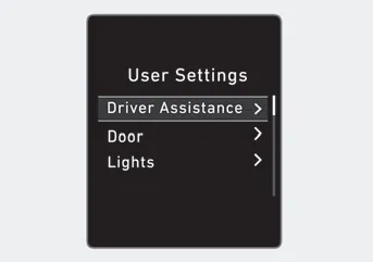
In this mode, you can change the settings of the instrument cluster, doors, lamps, etc.
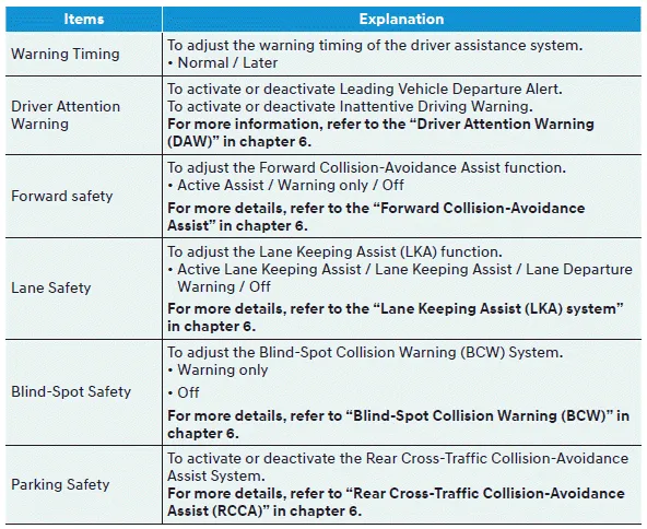
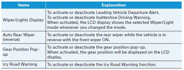
1. Driver assistance
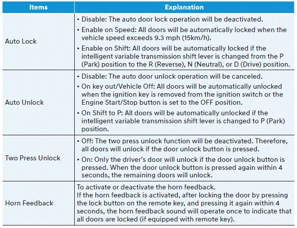
2. Door
3. Lights
4. Convenience
5. Service interval
6. Other
7. Language
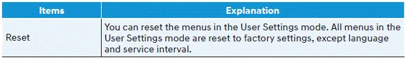
8. Reset
Edit settings after shifting to P
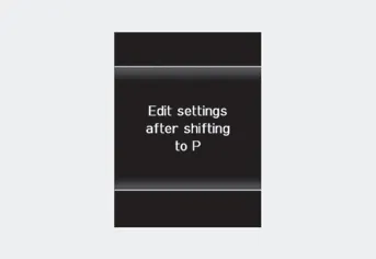
This warning message appears if you try to adjust the User Settings while driving.
Quick guide help
This mode provides quick guides for the systems in the User Settings mode.
Select an item, press and hold the OK button.
1. Driver Assistance
2. Door
3. Light

4. Convenience
5. Service interval
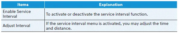
If the service interval is activated and the time and distance is adjusted, messages are displayed in the following situations each time the vehicle is turned on.
-- Service in: Displayed to inform the driver the remaining mileage and days
to service.
-- Service required: Displayed when the mileage and days to service has been reached
or passed.
Information
If any of the following conditions occur, the mileage and number of days to service may be incorrect.
-- The battery cable is disconnected.
-- The fuse switch is turned off.
-- The battery is discharged.
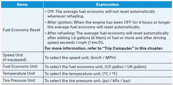
6. Other
7. Language

8. Reset
This warning light informs the driver the following situations. -- Forward Collision-Avoidance Assist system malfunction (if equipped) -- Forward Collision-Avoidance Assist radar blocked (if equipped) -- Blind-Spot Collision Warning system malfunction (if equipped) -- Blind-Spot Collision Warning radar blocked (if equipped) -- Lamp malfunction (if equipped) -- High Beam Assist malfunction (if equipped) -- Tire Pressure Monitoring System (TPMS) malfunction (if equipped) The Master Warning Light illuminates if one or more of the above warning situations occur.
The trip computer is a microcomputercontrolled driver information system that displays information related to driving. Information Some driving information stored in the trip computer (for example Average Vehicle Speed) resets if the battery is disconnected.
Other information:
Hyundai Venue (QX) (2020-2026) Service Manual: Repair procedures
Refrigerant System Service Basics (R-134a) Refrigerant Recovery Use only service equipment that is U.L-listed and is certified to meet the requirements of SAE J2210 to remove HFC-134a(R-134a) from the air conditioning system.
Hyundai Venue (QX) (2020-2026) Service Manual: Intake Actuator. Repair procedures
Inspection 1. Turn the ignition switch OFF. 2. Disconnect the intake actuator connector. 3. Verify that the intake actuator operates to the fresh position when connecting 12V to terminal 3 and grounding terminal 4.
Categories
- Manuals Home
- Hyundai Venue Owners Manual
- Hyundai Venue Service Manual
- Operating Door Locks from Outside the Vehicle
- Rear Seat Assembly. Repair procedures
- Electronic Stability Control (ESC)
- New on site
- Most important about car
